% "Filter design" lecture notes (EE364) by S. Boyd
% (figures are generated)
%
% Designs a linear phase FIR lowpass filter such that it:
% - minimizes the filter order
% - has a constraint on the maximum passband ripple
% - has a constraint on the maximum stopband attenuation
%
% This is a quasiconvex problem and can be solved using a bisection.
%
%   minimize   filter order n
%       s.t.   1/delta <= H(w) <= delta     for w in the passband
%              |H(w)| <= atten_level        for w in the stopband
%
% where H is the frequency response function and variable is
% the filter impulse response h (and its order/length).
% Data is delta (max passband ripple) and atten_level (max stopband
% attenuation level).
%
% Written for CVX by Almir Mutapcic 02/02/06

%********************************************************************
% user's filter specifications
%********************************************************************
% filter order that is used to start the bisection (has to be feasible)
max_order = 20;

wpass = 0.12*pi;        % passband cutoff freq (in radians)
wstop = 0.24*pi;        % stopband start freq (in radians)
delta = 0.5;            % max (+/-) passband ripple in dB
atten = -35;      % stopband attenuation level in dB

%********************************************************************
% create optimization parameters
%********************************************************************
m = 30*max_order; % freq samples (rule-of-thumb)
w = linspace(0,pi,m);

%*********************************************************************
% use bisection algorithm to solve the problem
%*********************************************************************

n_bot = 1;
n_top = max_order;
n = Inf;

disp('Rememeber that we are only considering filters with linear phase, i.e.,')
disp('filters that are symmetric around their midpoint and have order 2*n+1.')
disp(' ')

while( n_top - n_bot > 1)
    % try to find a feasible design for given specs
    n_cur = ceil( (n_top + n_bot)/2 );

    % create optimization matrices (this is cosine matrix)
    A = [ones(m,1) 2*cos(kron(w',[1:n_cur]))];

    % passband 0 <= w <= w_pass
    ind = find((0 <= w) & (w <= wpass));    % passband
    Ap  = A(ind,:);

    % transition band is not constrained (w_pass <= w <= w_stop)

    % stopband (w_stop <= w)
    ind = find((wstop <= w) & (w <= pi));   % stopband
    As  = A(ind,:);

    ptop = 10^(delta/20);

    % This is the feasibility problem:
    % cvx_begin
    %      variable h_cur(n_cur+1,1);
    %      10^(-delta/20) <= Ap * h_cur <=  10^(+delta/20);
    %      abs( As * h_cur ) <= +10^(+atten/20);
    % cvx_end
    % Unfortunately, the solvers often struggle with this formulation. For
    % this model, there is a logical optimization problem: minimize the
    % stopband attenuation. If the minimum attenuation is below the target,
    % then we know the original problem is feasible.
    cvx_begin quiet
         variable h_cur(n_cur+1,1);
         minimize( max( abs( As * h_cur ) ) );
         10^(-delta/20) <= Ap * h_cur <=  10^(+delta/20);
    cvx_end

    % bisection
    if isnan( cvx_optval ),
        fprintf( 1, 'Solver failed for n = %d taps, assuming infeasible\n', n_cur );
        n_bot = n_cur;
    elseif cvx_optval <= 10^(atten/20),
        fprintf(1,'Problem is feasible for n = %d taps\n',n_cur);
        n_top = n_cur;
        if n > n_cur,
            n = n_cur;
            h = h_cur;
        end
    else
        fprintf(1,'Problem not feasible for n = %d taps\n',n_cur);
        n_bot = n_cur;
    end
end

h = [ h(end:-1:2); h ];
fprintf(1,'\nOptimum number of filter taps for given specs is 2n+1 = %d.\n', length(h));

%********************************************************************
% plots
%********************************************************************
figure(1)
% FIR impulse response
plot([-n:n],h','o',[-n:n],h','b:')
xlabel('t'), ylabel('h(t)')

figure(2)
% frequency response
H = exp(-j*kron(w',[0:2*n]))*h;
% magnitude
subplot(2,1,1)
plot(w,20*log10(abs(H)),...
    [wstop pi],[atten atten],'r--',...
    [0 wpass],[delta delta],'r--',...
    [0 wpass],[-delta -delta],'r--');
axis([0,pi,-50,10])
xlabel('w'), ylabel('mag H(w) in dB')
% phase
subplot(2,1,2)
plot(w,angle(H))
axis([0,pi,-pi,pi])
xlabel('w'), ylabel('phase H(w)')
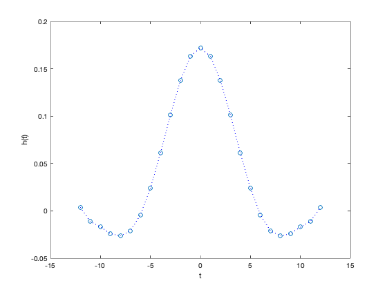
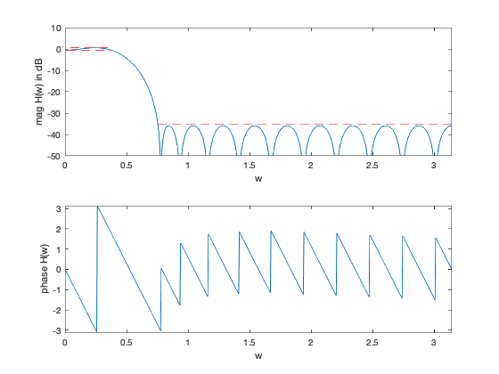
Rememeber that we are only considering filters with linear phase, i.e.,
filters that are symmetric around their midpoint and have order 2*n+1.

Problem not feasible for n = 11 taps
Problem is feasible for n = 16 taps
Problem is feasible for n = 14 taps
Problem is feasible for n = 13 taps
Problem is feasible for n = 12 taps

Optimum number of filter taps for given specs is 2n+1 = 25.